Overview
I’ve created a PCB to interact with MySensors. The board can be powerd from any source between 3.5v and 5.5v, and will generate 3V3 for the nRF24l01(+) module. It has 14 IO’s and footprints for a DHT11/DHT22 and a DS18B20 temperature sensor.
Features
- On-board, software configurable, 3V3 regulator
- Current in shutdown mode: 7µA
- Supports nRF24l01(+) (PA/LNA) wireless module
- VCC from 3.5V to 5.5V
- 2 PWM 3mm LED footprints
Temperature sensors
The interface board has 2 onboard temperature sensors.
- DS18B20
- DHT11/DHT22
The DS18B20 has a temperature accuracy of ±0.5°C from -10°C to +85°C.
The DHT11 has a temperature accuracy of ±2°C from 0°C to +50°C and a humidity accuracy of 5% from 20% to 80%.
The DHT22 has a temperature accuracy of ±0.5°C from -40°C to +80°C and a humidity accuracy of 2-5% from 0% to 100%.
Optional crystal
A footprint for a standard crystal is present, yet not required to populate. If precise timings are required, use of an external crystal is recommended as the internal oscillator of the ATmega328p has an accuracy of 10% without calibration.
Power consumption
The unit consumes about 3.5µA (or 10.5µW) in sleep state. When sending some data, around 9mA is drawn for about 10ms. All translated, it should be able to run for at least a year, powered by a CR2032, when sending some data every minute.
Schematic
Click to open the schematic: MySensors Rev00 Schematic PDF
Validation
Tested and verified
- DHT11(22)
- DS18B20
- NRF24L01+ (PA-LNA)
- Program header
- 3V3 LDO with software enable
- 2 output LEDs
Hardware
The schematic and board files are made in Altium CircuitMaker.
The nrf24l01(+) module is powered by the MIC5205-3.3 LDO. The enable pin is connected to pin PB8 (D8) of the µController (Atmega328p) which enables a complete shutdown of the 3V3 peripherals via software. Keep in mind, when using a MySensors sketch, you’ll have to enable and set the output pin high in order to communicate with the wireless module.
The VCC of the PROGRAM header can be detached from VCC by the jumper above the header.
Powering up the board
To power up the board you can apply a voltage source of minimum 3.5V and maximum 5.5Vvia
- The programmer, if you short the jumper (J1) above the program header
- Connect the power via any of the VIN and GND pins
Programming
You can program the board via any ISP programmer (USBasp, Arduino as ISP, USBtinyISP, …). The pinout of the ICSP header can be found here. In the Arduino IDE, choose USBasp/USBtinyISP/Arduino as ISP as the programmer and ‘Arduino Pro or Pro Mini’ as the board. Next choose ‘ATmega328 (3.3V, 8MHz)’ as the processor. Upload sketches via ‘Sketch -> Upload with programmer’ or CTRL/CMD + SHIFT + U.
MySensors
Download the MySensors library via the library manager of the ArduinoIDE. The default connection of the CE and CSN in the MySensors library are the same as the MySensors Interface Board. No changes are needed. The only thing you’ll have to manually add to each sketch is setting 3V3 enable high. This is pin 8 (in the Arduino IDE). Otherwise the NRF24L01(+) module won’t power up. This is implemented to completely shut down the wireless module to save power.
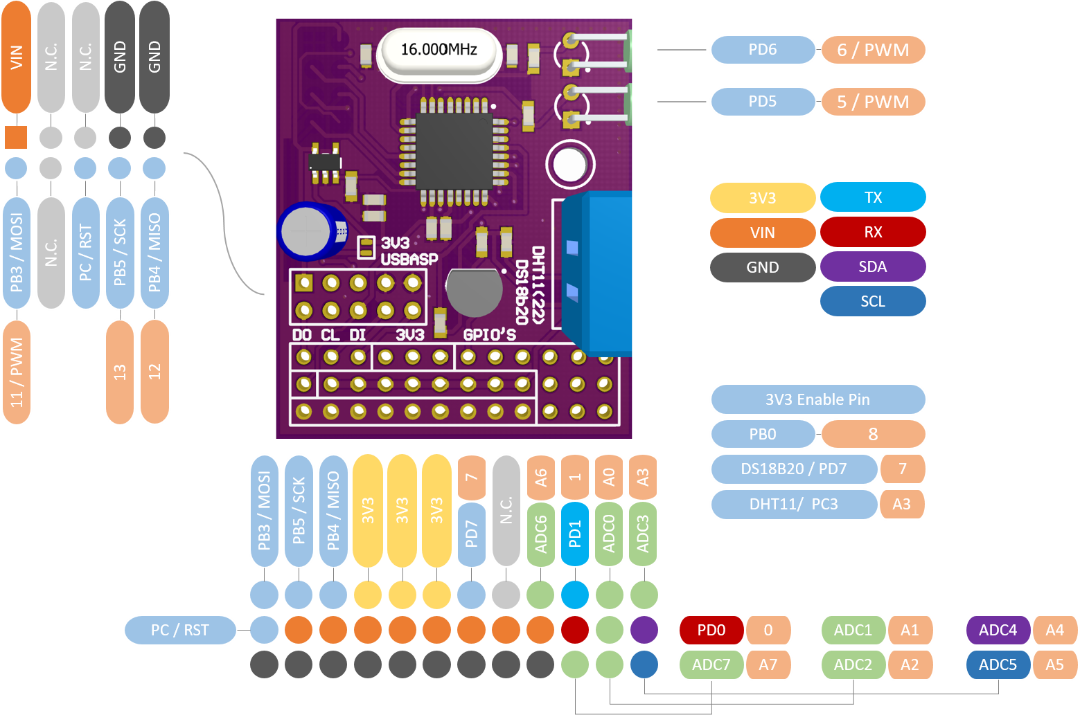
Pin Assignment
- Light orange represents the Arduino IDE pin
- Light blue represents the physical atmega328p pin
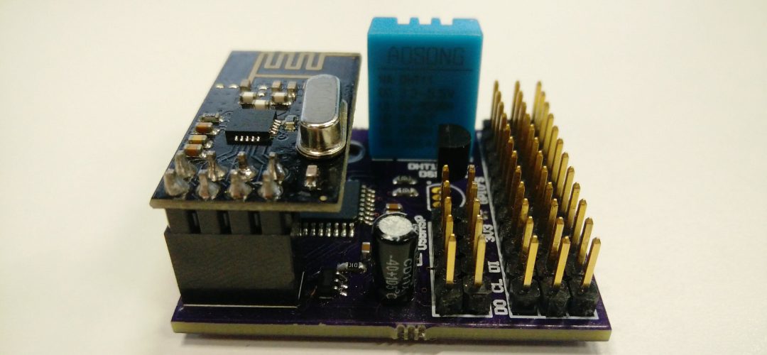
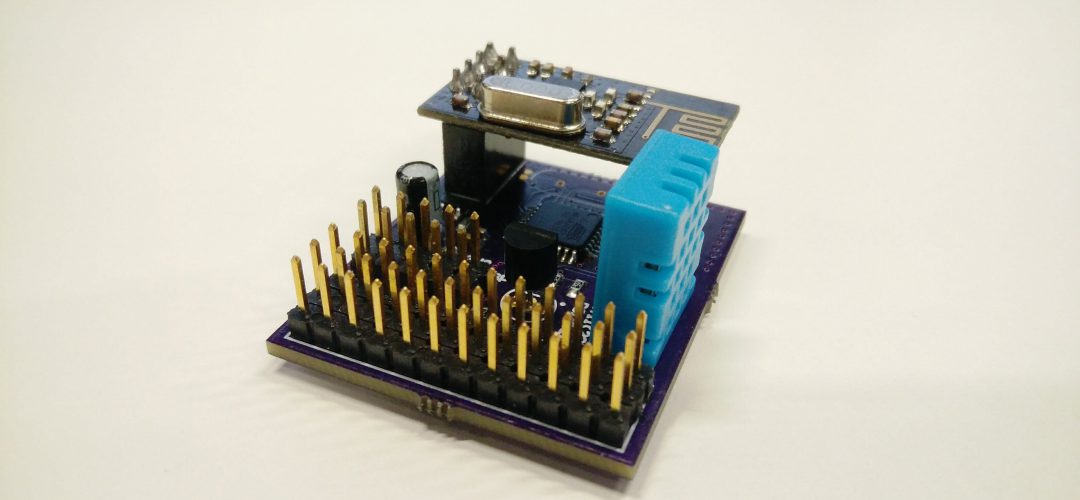
Board photos
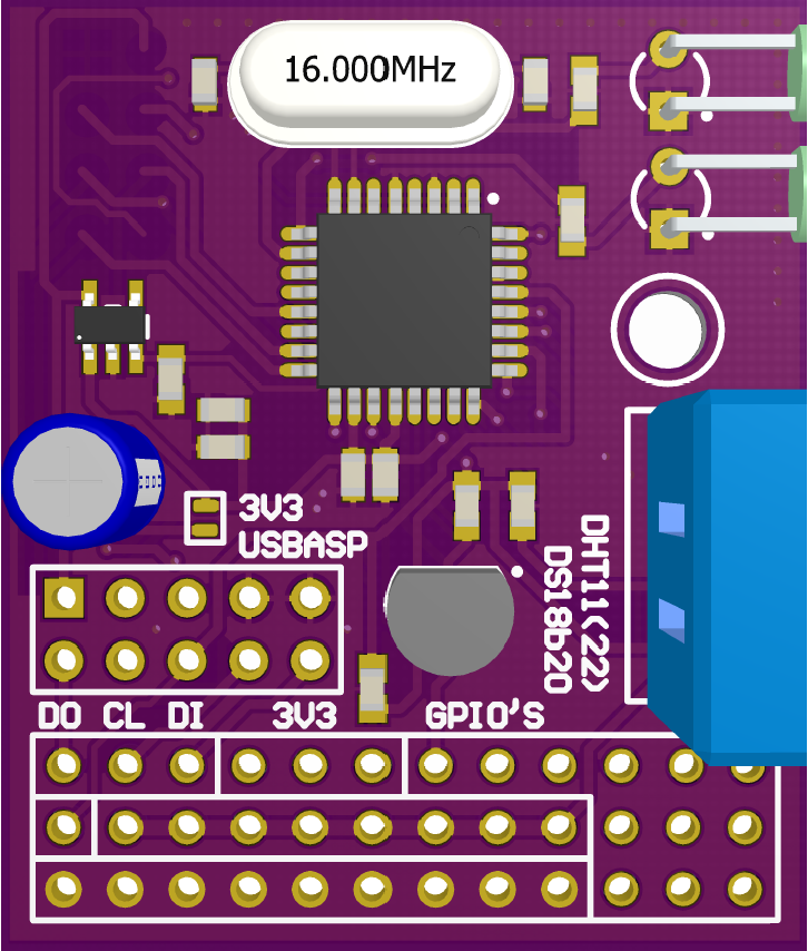

Top without nRF24L01(+)
Top with nRF24L01(+)
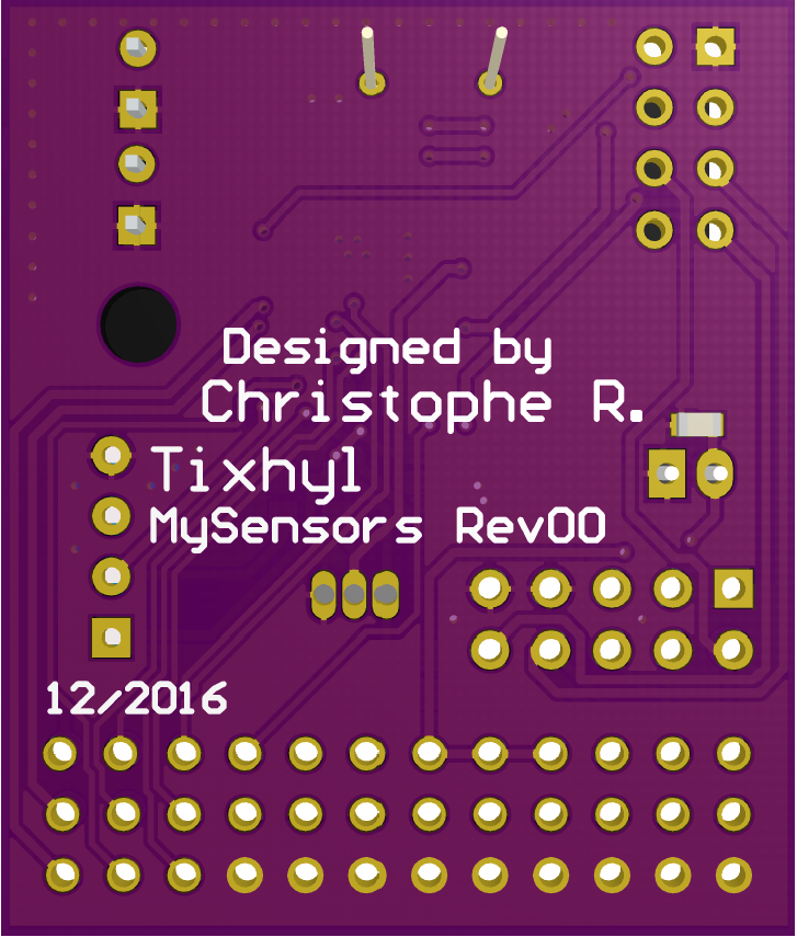
Bottom